The importance of solid control equipment is its ability to save costs of dumping drilling fluids due to the existence of unwanted solids inside. As we are drilling the well, the cuttings will appear in the mud, and further treatment is necessary.

Shale Shakers
The design of shaker screens allows them to remove the particles which will not pass through the mesh. At the same time, the vibration of the screen will control blinding or plugging, which would lower its efficiency. The mesh size on most shale shakers is 10 – 14 API mesh. (A 10 mesh screen has ten openings per inch along each side). Many cuttings will pass through the ten mesh screens since they have disintegrated due to erosion and hydration. For this reason, we may use a finer mesh (80 openings per inch). In addition, we may arrange the screens in series so that a finer mesh is beneath the coarser mesh.
Sometimes, we arrange the screens in parallel to control larger volumes of solids, with a slight overlap to ensure in the equipment, no cuttings bypass the screening. We must remember that using a finer screen minimizes the screen’s flow area. While drilling a surface hole, we will have to screen a large volume of cutting, so there may be a physical limitation on the mesh size (unless increasing the screen area).

Hydrocyclone Equipment For Solid removal
The primary application of hydrocyclones is to remove all the sand particles and most of the silt particles from the mud while retaining the colloidal fraction. Hydrocyclone is a general term that includes desanders & desilters – desanders (6″ diameter or greater), desilters (generally 4″ diameter)- and clay ejectors (2″ diameter). The operating principle of the hydrocyclone is the same irrespective of size (Figure 18). A centrifugal pump feeds mud tangentially at high speed into the housing, thus creating high centrifugal forces. These forces, which multiply the settling rate, will throw the heavy particles against the outer wall and descend them toward the outlet (underflow). The lighter particles move inwards and upwards as a spiraling vortex to the liquid discharge (overflow).
The design of hydrocyclones allows passing only solids (plus a small volume of fluid) out of the underflow. This process should appear as a “spray discharge” and not a “rope discharge”. Rope discharge indicates solids overloading, and the underflow will soon plug off completely.

Operations
Figure 18 shows the regular operation of hydrocyclone equipment for solid control. The hydrocyclone cut point is the particle size at which 50% of the particles of that size will be discarded (Figure 20). A typical cut point for a desilter is 20 microns, and a desander is 40 microns. Since barite particle size lies between 2 and 80 microns, we can’t run hydrocyclones with weighted muds since it would remove about half the barite through the underflow.
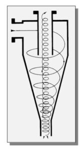
Notice that for a clay ejector (Figure 19), the outlets are reversed (i.e., the underflow containing valuable barite is returned to the active system while the overflow containing finer material is discarded). We install such devices for barite salvage for weighted muds. Notice that the separation mechanism will be due to particles (with different densities) settling action.

Decanting Centrifuge Equipment For Solid Control
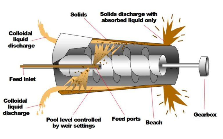
The introduction of the first oilfield Centrifuges was to control solids and retain the barite in weighted water-based muds. However, we may also use them in unweighted muds and oil-based muds to process the hydrocyclone underflow and return the liquid colloidal fraction to the active system. Figure 21 shows a decanting centrifuge. It consists of a rotating cone-shaped bowl and a screw conveyor. The high-speed rotation of the centrifuge will throw the heavier particles against the bowl side. The screw conveyor moves these particles along the bowl and carries them toward the discharge port. At the opposite end is another port where it discharges the liquid containing the finer particles. For weighted mud, the underflow from the shale shaker will move to the centrifuge (no hydrocyclones used). The solids discharged through the underflow contain valuable barite that will return to the active system.
For barite salvage, centrifuge equipment is more efficient than hydrocyclones in solid control since they make a finer particle cut. Under proper operating conditions, we can salvage 90 – 95% of barite. When drilling hydratable shales, we must control the finer drill solids. The finer solids in the liquid phase are typically discarded, although this will also contain chemicals and barite. For unweighted mud, the underflow from the desilters will move to the centrifuge. This time the liquid phase, including the fine material (including bentonite), will return to the mud, while there will be a discard for the solids. We often use this technique in oil-based as the base oil is costly to replace. Water-wet solids in an oil-based mud can be challenging to control, but a centrifuge can separate them from the liquid-colloidal phase. Also, we will have to dump the solids because we can’t reuse them.
Mud Cleaner

A benefit of mud cleaner equipment is to control drill solids larger than barite. It consists of a desilter and a screen and removes solids in two stages. We use it for weighted mud to remove solids while retaining barite. First, the drilling fluids pass through the shale shaker, which should be as fine as possible and still accommodate the full mud flow. Then, the underflow will pass through a bank of desilters, where the overflow (lighter material) will return to the active system. After that, the underflow will move onto the screen (usually 150 – 200 mesh). The barite particles will pass through and return to the system (together with very fine solids). The solids, which the screens will separate, will be discarded.
Most drilling mud companies have developed Mud cleaners under the names “silt separator” or “sand separator”. We can use them with decanting centrifuges to process both weighted and unweighted mud as oil-based mud. They are best suited for drilling fluids less than 15 ppg. (For heavier drilling fluids, a centrifuge is better.)
5.2 Solids Control Systems
The configuration of the above components will be in such a way as to remove the unwanted solids as efficiently as possible while ensuring that there will be no removal for the mud chemical (OBM additives – WBM chemicals) & solids (Bentonite & Barite).
Unweighted Muds
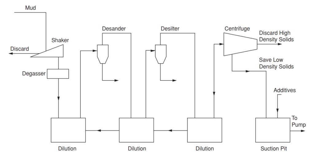
When configuring a system for an unweighted mud (Figure 22), the arrangement of various solids control components in decreasing order of removed particle size is essential to prevent clogging. Dilution is also vital for upstream of hydrocyclones to increase their separation efficiency. If passed through the solids control equipment, the mud should consist of water, well-dispersed bentonite, and very fine drill solids. It can then be diluted, treated with chemicals, and conditioned before re-circulating.
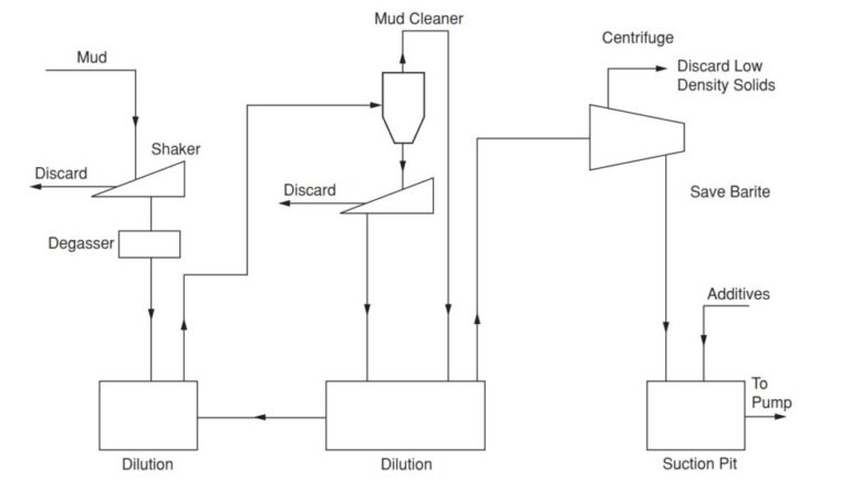
Weighted Muds
Hydrocyclones cannot be used alone for weighted mud (Figure 23) since they will discard barite. We may use mud cleaner, however, to overcome this problem. As with unweighted mud, water is necessary for diluting upstream of the mud cleaner and the centrifuge. Notice that the low-density solids in the liquid phase are discarded from the centrifuge while retaining the solids (barite). We must also replace the chemicals and bentonite dumped with the liquid phase. The optimum solids content in a weighted mud is difficult to determine.